WiFi USB Switch
Sinilink WiFi USB switch
I saw a Youtube video showing Sinilink WiFi USB switches being flashed with Tasmota. I bought a few on Alibaba.
I aim to use them to power some USB devices instead of the current Sonoff S26 smart switches they use currently.
I found some other blogs (1) (2) also documenting this process but I still wanted to detail my process, particularly the wiring in more detail.
Flashing to Tasmota with Tasmotizer
The default software on the sticks has been said to be buggy so going with the open source Tasmota is a better idea. To do this using Tasmotizer makes it easy.
To flash them I did not have a USB FTDI so instead aimed to use a Raspberry Pi 3 B+.
Setting up the Raspberry Pi
My first attempts to installs failed as my Raspberry Pi had a very old image so I downloaded and installed a new OS using the Raspberry Pi Imager.
As the serial port is needed I opened the Raspberry Pi Configuration and under Interfaces set Serial to Enabled. I left Serial Console as Disabled.
The docs state that only one command would be needed to install:
sudo python -m pip install tasmotizer
This installed okay but running the app would fail with an error: No module named 'PyQt5.QtSerialPort'
To resolve this I ran:
sudo python -m pip install PyQt5.QtSerialPort
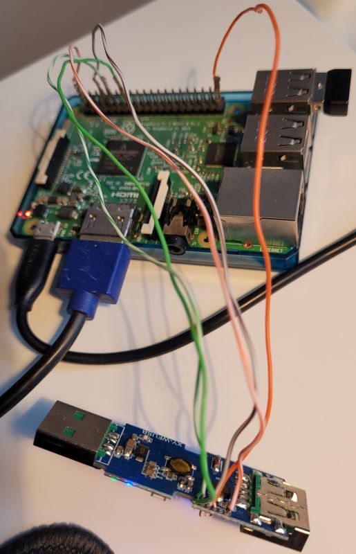
Wiring
I used the information from blakadder.com. I worked with the Sinilink button side up with the USB-male pointing to my left the same as the links images.
| Sinilink | Pi |
|---|---|
| (1) GND | (14) GND |
| (2) TX | (10) RX |
| (3) RX | (8) TX |
| (4) GPIO 0 | (39) GND |
| (5) RST | |
| (6) 3.3V | (1) 3.3V PWR |
I used 5 pieces of wire extracted from a short length of Ethernet cable. The 3.3V wire should be the last one connected.
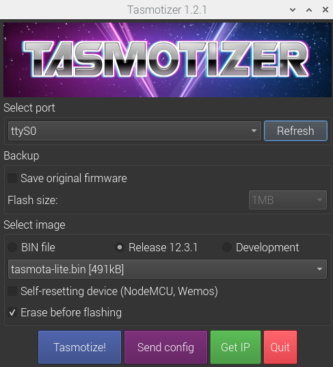
Flashing
Launch Tasmotizer using:
python /usr/local/bin/tasmotizer.py
- Choose port. For me
ttyS0 - Choose
Release. For me12.3.1, I usedtasmota-lite.bin - Click
Tasmotize!
Configuring
- Disconnect the USB switch from the Pi
- Plug the USB switch in to a powered USB port
- On your laptop/phone and search for and connect to the WiFi SSID with a name like
tasmota-*followed by some random numbers - You device should auto redirect to
192.168.4.1 - Populate
WiFi NetworkandWiFi Passwordand hitSave - Your device should drop off the
tasmota-*SSID and reconnect to your WiFi Network and be redirected to the new IP address of the USB Switch - In
Configure»Configure Otherpopulate:Templatewith:{"NAME":"XY-WFUSB","GPIO":[1,1,0,1,32,224,0,0,0,0,320,0,544,0],"FLAG":0,"BASE":18}- Check
Activate - This template is taken from blakadder.com
- Check
Device NameandFriendly Name 1to whatever you like
- Click
Saveand the USB switch will restart - In
Configuration»MQTTpopulateHostand others if needed - Click
Saveand the USB switch will restart
Integrating with Home Assistant
If your flashing/configuration has been done correctly and you already have MQTT set up then the Tasmota integration with automatically discover your new devices.